Underwater VR for Astronaut Training

Abstract
Pools are excellent places for testing many nautical technologies, as well as training divers or astronauts in simulated weightlessness. However, for extensive astronaut training underwater, a large pool is necessary. The Neutral Buoyancy Laboratory (NBL) is an astronaut training facility and located at the Sonny Carter Training Facility, near the Johnson Space Center in Houston, Texas, containing 23 million liters of water. In Europe, Blue Abyss Ltd. is currently building the world’s largest and deepest indoor pool in Cornwall, also having space applications in mind. We believe that a VR solution can overcome the needs for large pools for astronaut training as space equipment can be well-simulated in virtual reality. To this end, we combined a full-face diving mask with a custom built VR headset for simulating a space environment. Besides constructing a water-tight VR headset, a precise tracking system to determine the position and orientation in space plays an important role. We use an outside-in tracking system consisting of four cameras in watertight housings, mounted on aluminium rails, covering a 23.5 meter experimental area, which enable us to track reference markers placed on the underwater VR diving mask. To calibrate this system, a rectangular cuboidal structure with reference markers is placed in the experimental area, which additionally serves as a handrail to perform basic Extra Vehicular Activity (EVA) tasks. The position tracking of the underwater headset and mirroring of physical objects in VR enables the user to move physically in the virtual environment as well as interact with the physical objects, such as the handrail. Due to the underwater environment, refraction at different media needs to be taken into account for both calibration and tracking.
Keywords and phrases:
Head Mounted Display, VR Glasses, Underwater, Motion TrackingCopyright and License:
Andreas Nüchter; licensed under Creative Commons License CC-BY 4.0
2012 ACM Subject Classification:
Human-centered computing Empirical studies in visualization ; Human-centered computing Visualization theory, concepts and paradigmsAcknowledgements:
We also acknowledge support from the Elite Network of Bavaria for the academic program Satellite Technology – Advanced Space Systems. We also thank Helene Klein for investigating the end-to-end delay of the VR glasses.Funding:
The work was performed at Julius-Maximilians-Universität Würzburg under the ESA OSIP study ESA AO/2-1830/22/NL/ GLV/ov and the funding is greatfully acknowledged.Supplementary Material:
Audiovisual (video demonstrating the approach): https://youtu.be/rKG1XqJKrDw [6]Editors:
Leonie Bensch, Tommy Nilsson, Martin Nisser, Pat Pataranutaporn, Albrecht Schmidt, and Valentina SuminiSeries and Publisher:
1 Introduction
“Diving is the poor man’s spacewalk”, a saying frequently used by diving instructors in their beginner courses just before students take their first plunge underwater. The European Space Agency (ESA) states on its homepage that ”Training underwater is as close as it gets to experiencing weightlessness on Earth so spending time in a full spacesuit is used to practise techniques for spacewalks and neutral buoyancy is substituted for microgravity.” [2].
The world’s largest indoor swimming pool is NASA’s Neutral Buoyancy Laboratory (NBL) in Houston, Texas, boasting a capacity of over 23 million liters of water. However, even with dimensions of 623112 meter, it’s still not large enough to house a complete model of the International Space Station (ISS). Instead, specific modules are swapped in and out as needed. In Cologne, Germany, the European Space Agency (ESA) operates the Neutral Buoyancy Facility (NBF), an octagonal-shaped indoor pool measuring 221710 meter and holding 3.7 million liter of water. Despite their immense utility for astronaut training, the operation and maintenance of such facilities is a complex and expensive endeavour.
Virtual Reality (VR) involves simulating a virtual environment, projecting it onto 3D near-eye displays, and adjusting the view based on system movements to fully immerse the user. VR has gained significant popularity, especially within the gaming industry, following the launch of the Oculus Rift in 2012 and Facebook’s subsequent acquisition of Oculus VR in 2014. Nowadays, VR is utilized in various applications, such as entertainment for gaming, movies, and concert streams, in education for training professionals before undertaking difficult tasks (e.g., fire-fighting, mining or medical operations), and in archaeology to preserve heritage sites for future generations.

This works demonstrates that an underwater VR system serves very-well as a viable alternative to current astronaut training methods, offering the advantage of simulating large structures like the ISS in a small pool. This paper begins by providing background information on the decisions made during this endeavour, followed by a detailed description of the current system, a presentation of initial tests conducted, and concludes with an outline for future work.
2 Background
When developing an underwater VR system, one has to face certain challenges. Commercial VR headsets are meant to be used in air, which means they are not waterproof. Additionally, proprietary hard- and software is used, so accessing certain elements such as the sensors or image stream is not possible. When looking for off-the-shelve underwater VR headsets, the DIVR by Ballast VR [11] comes to mind. This is a watertight, cordless VR system, meant to be used in aquatic entertainment. They provide different virtual environments, and the system is meant to be used e.g. in water slides or while just snorkelling in a regular pool. Additionally, they offer a stationary thruster system, which emits fluctuating thrusts of water. However, the same as with classical VR headsets, neither the hardware nor sensors are accessible. Also, though named DIVR, the system is only certified of submersion up to 1.2 meters. Therefore, the decision was made to build a custom VR headset from scratch.
One of the most important aspects of virtual reality is the movement tracking of the head in order to adjust the projected images accordingly. On the other hand, the movements of real objects, e.g., tools, in the workspace should possibly also be tracked in order to be able to interact. In all cases, very high precision, update rate, and range of position measurements are critical. Tracking systems use a wide variety of technologies to determine the position in space. These include measurements via ultrasound, laser, mechanical coupling, gyroscopes, image processing systems, or hybrid systems. Independent of the chosen physical measurement method, a further distinction can be made between the position of the sensors and the reference to be measured, i.e., auxiliary objects (so-called beacons or markers) that are used for the actual position determination. These systems are categorized as either inside-out or outside-in tracking based on how they determine the position and orientation of the user’s head in relation to their surroundings. Inside-out tracking typically uses camera sensors to track feature points in the environment in combination with inertial sensors to estimate the head pose with respect to the environment. This requires integrating the camera sensors into the underwater headset, which makes the diving mask bulky and the setup more difficult for prototyping. Therefore, we opted for an outside-in tracking system based on four FLIR BFS-PGE-23S3C-C industrial cameras [3]. The tracking in work is achieved by marker detection via a set of four cameras, which are integrated in watertight housings and permanently submerged.
3 Hardware Setup
3.1 The VR Headset
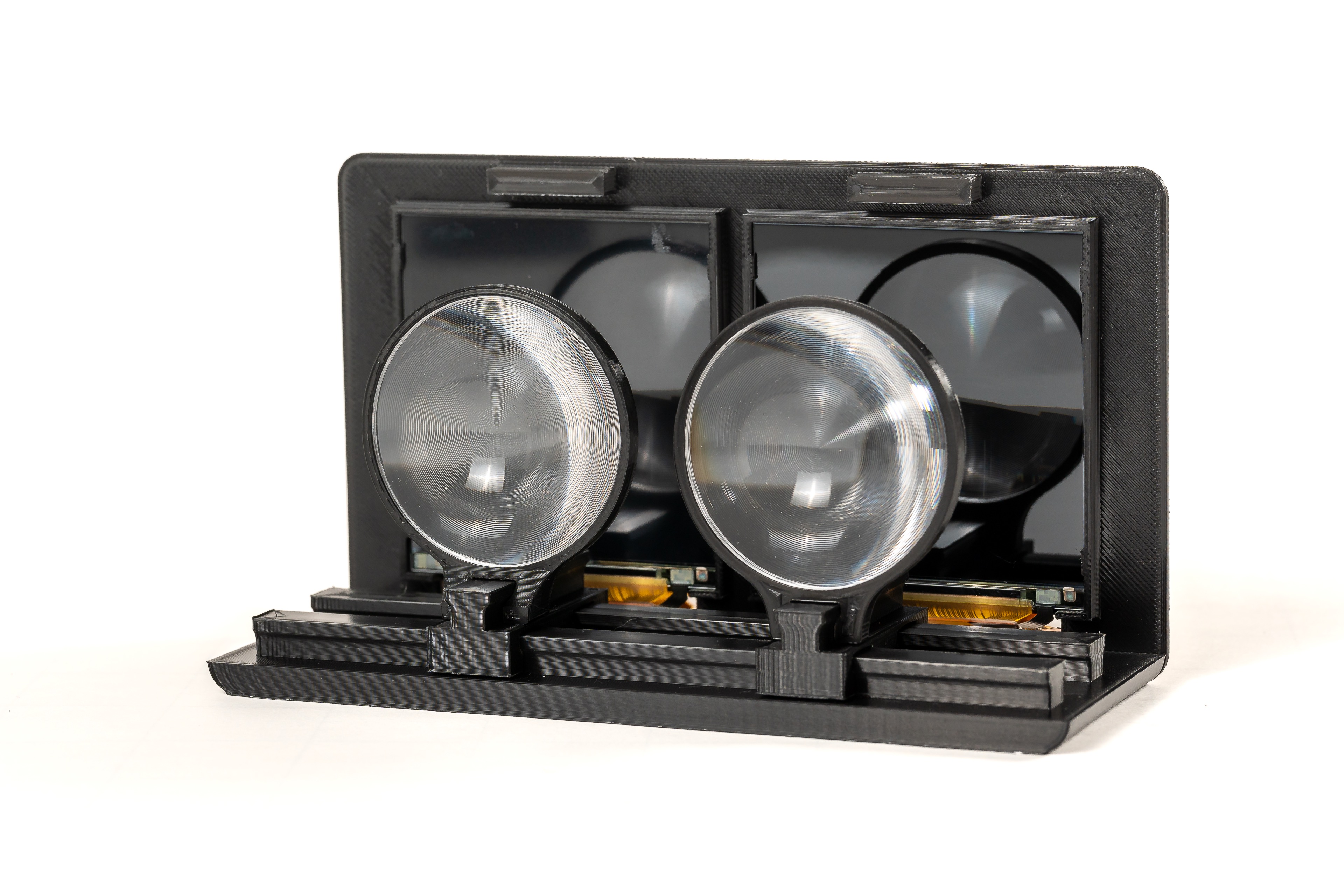
Building a budget VR headset from scratch is something, that, ever since Google launched the well-known, but now discontinued Cardboard [4] in 2014, has been the playground for many Makers around the world. As a starting point for this work, the open-source project Relativty [9] was chosen, since the recommended displays offer 2 K resolution at 120 Hz and the kit includes a Mobile Industry Processor Interface (MIPI) to Mini Display Port (mDP) controller board, which is powered using Micro USB, while being still affordable with around 200 USD. To test the basic functionality, a small mock-up was designed and 3D printed, cf. Fig. 2. Two Fresnel lenses with a focal length of 50 mm are mounted on a sliding mechanism, in order to adjust for different interpupillary distances and visual acuities. The displays are connected via the controller board to a desktop PC. This mock-up was used to provide an easy and simple handheld device to work on the virtual environment and the tracking, as described in the next two sections, while adapting the VR headset onto a diving mask.

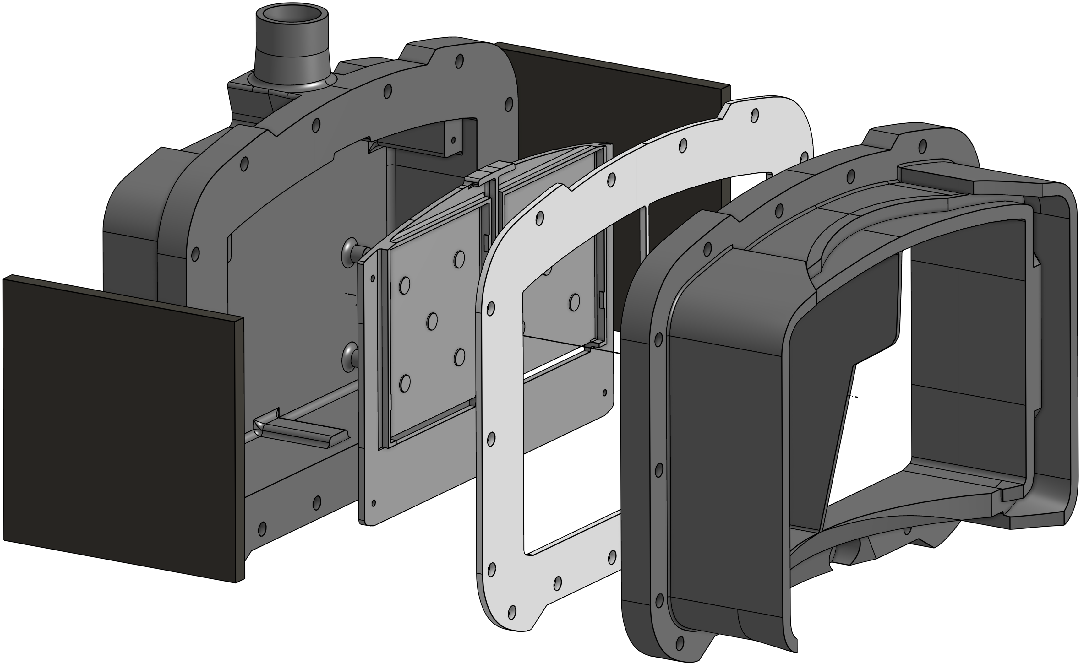
The diving mask chosen is the Interspiro Divator Full Face Mask [5], due to it being widely spread amongst professional divers, as well as being used by the European Space Agency (ESA) for their underwater astronaut training. The design consists of six different parts, shown in Fig. 2. The first part in dark grey on the right is specifically modelled to fit onto the shape of the Divator visor. It is glued onto the mask and sealed off with a waterproof silicone to fill all remaining gaps between the visor and the part. Next, shown in light grey, is a laser-cut 2 mm silicone gasket. The part in medium grey is a mounting plate for the displays, which is screwed onto the left part, again in dark grey, that contains the controller board and an outlet for the power and display cables. The casing is bolted together with 16 stainless steel screws and nuts, and 32 stainless steel washers to redistribute the clamping force. The two black parts show in Fig.2 are attachment plates for reference markers. To safely guide the power and display cables to the surface, a 22 mm silicone tube is clamped to the cable outlet. One of the biggest challenges of underwater VR is water tightness. Therefore, the whole casing in rev1 was 3D printed with 100 % infill using a FDM (fused deposition modeling) printing. Additionally, any grooves on the connecting surfaces touching the silicone gasket are filled with a waterproof epoxy, sanded down, spray coated, and again sanded down for maximum smoothness. In rev2 resin printing, also known as SLA (stereolithography) has been used. Rev3 was made all-alluminium using milling. Here we have replaced the silicone gasket with an O-ring.
Since all electronics are enclosed and bolted down in the watertight housing and adjusting the lens-to-lens and lens-to-screen distances would be tedious if integrated within the housing, they needed to be mounted inside the mask itself. The Interspiro Spectacle Kit is a solution by Interspiro to use custom lenses with a diving mask. It comes with a mounting frame, which is put inside the mask, and a lens holder, which attaches to the mounting frame via an up-and-down-slideable rubber piece. Since the lens holder is angled and does not accept sound lenses, a custom lens holder was designed and 3D printed to accommodate the Fresnel lenses. To adjust for different interpupillary distances, multiple pieces with 60 mm to 65 mm center-to-center distance are available. To adjust for different visual acuities, the connecting pins are 8 mm long. Also, the lens holder is designed such that the lenses are mounted parallel to the displays. The mounting frame and the lens holder are shown in Fig. 3.
The complete VR diving mask is shown in Fig. 3. The connected cables are an optical mDP to DP cable and a Micro-USB Cable, both 10m long, to accommodate for diving depths of 3 m in a 33 m pool while providing enough length to connect to a PC, located next to the pool.
3.2 The Virtual Environment
The two scenes shown in Fig. 4 are implemented in the Unity game engine. To create the necessary output stream for the VR headset, a dummy body with two cameras with an interpupillary distance of 60 mm as ”eyes”. The video stream sent to the VR headset has a resolution of 28801440 pixels, split vertically into two equal parts for the left and right eye.
One of the goals defined by ESA was to have the Lunar Gateway Space Station as the central objective in the modeled game environment. As there already exist numerous 3D models on the Internet under open licenses, one of these models was selected to be utilized for this project. The chosen model111https://www.artstation.com/marketplace/p/5j9Jv/gateway?utm_source=artstation&utm_medium=referral&utm_campaign=homepage&utm_term=marketplace provides Unity Universal Render Pipeline (URP) files to embed it directly into Unity. The exact dimensions and positions of the objects in relation to each other have been preserved in Unity, so they match the dimensions of the real objects.
3.3 The Tracking System
Head tracking systems are used in various applications, including virtual reality (VR), augmented reality (AR) and human-computer interaction, to estimate the movement of a user’s head. In our setup, four cameras are placed on opposite sites around the workspace on aluminium bars with a camera-to-camera distance of about 1.8 m and a bar-to-bar distance of about 3.4 m. On the underwater headset, AprilTag [8] fiducial markers are fixed to allow 6-DoF tracking of the head pose if at least one marker is visible. The cameras are mounted approximately 0.3 m above the ground, tilted inwards by 30 ∘ and upwards by 15 ∘ to ensure good coverage of the workspace. A schematic overview of the setup is shown in Fig. 5, top.

The cameras are integrated into underwater housings with acrylic viewports and are connected via Ethernet to a computer outside the pool for image processing and motion estimation. In water the viewport acts like an optical element. Due to the change in refractive index between water, glass and air, refraction occurs. In order to minimize the effect of refraction, dome ports are employed. Dome ports are built from a hemispherical glass shell and aim to minimize the geometric changes of the light path. If the camera center is aligned with the center of the dome port, the ray from the object through the center of projection to the image point is perpendicular to the spherical media interfaces. Therefore, no refraction occurs, and a near-perfect central projection is provided. The advantage of the dome port is that the field of view and image distortions are unchanged if the camera is centered. However, the depth of field increases slightly, and the focus distance is different compared to air. The spherical interface acts similarly to a negative lens element. Hence, the objects captured through the dome port appear to be closer.
Examples of a dome port and flat port underwater housing are shown in Fig. 6. The top left image shows a dome port housing that is rated for a depth of 750 m. The flat port housing depicted in the top right images features a 19mm thick glass window and a depth rating of 1750 m. In the two housings, two industrial machine vision cameras are integrated. Below the housings, example images of the two underwater cameras are shown. The images are captured with the dome port and flat port partially submerged in water.
The top half of the images is in air, while the lower half is in water. The dome port image shows little geometric distortion of the captured chessboard, which suggests that the camera is well-centered in the hemispherical glass window. The sharpness of the image is noticeably different for the part of the image in air and water since the camera needs to be focused at different distances. Here, the camera-lens system was focused for the in-water conditions. The bottom right image visualizes the different magnifications of the flat port interface in air and in water. The chessboard appears closer in the lower half of the image captured in water. The magnification and focal length of the combined camera and housing system are increased.
We align the camera based on the manufacturers specification of the position of the entrance pupil of the lens. Smaller errors in alignment are compensated by in-situ camera calibration [1]. We do not apply a specific underwater camera model but assume that the errors are absorbed by the radial and tangential distortion model. The cameras are individually calibrated in water using a calibration board. The extrinsic parameters of the cameras are estimated online using AprilTag markers placed on a fixed structure in the center of the workspace. This way, the setup can be easily reconfigured without performing re-calibration. The cameras are synchronously triggered and deliver an image stream with up to 80 Hz. For each image set, the head pose is computed by minimizing the reprojection errors of the projection of all visible AprilTag marker corners on the individual camera sensors. After head pose estimation, filtering is applied to smooth the pose output and avoid erroneous fast movements due to tracking failure, which would negatively affect the user.
All structures are build from aluminium bars with aluminium and stainless steel connectors, the cameras are mounted with 3D-printed attachments made from PET. The center piece is a 110.42 m cubic shaped structure. 8 mm PVC foam boards with printed on makers are mounted on all four sides and the top. On top of the structure, a 30 mm diameter aluminium rod is mounted about 0.5 m above ground and acts as a handrail to perform basic EVA movements.
The data processing of the camera streams runs on a dedicated workstation PC (i9-13900KS, 64 GB RAM). All cameras are connected to a 10 GBit/s Switch, to allow for the simultaneous transfer of four 2.3 MP video streams at up to 80 Hz. The data processing is done with the Robot Operating System (ROS) [10, 7], which provides the pose of the tracked headset via a ROS-to-Unity bridge. The Unity simulation listens to the data processing for updates on the current headset pose and moves the virtual cameras accordingly.
For the final version of the headset, i.e., rev3 as described above, an inertial sensor is used in addition to optical tracking, which is also integrated into the headset. For this purpose, the BNO085 IMU breakout board from Adafruit was selected, which is equipped with the BNO085 inertial measurement unit from CEVA Technologies, Inc. The sensor employs the same hardware as the Bosch Sensortech BNO055, but with an optimized firmware specifically designed for AR/VR applications. An Arm Cortex M0 processor is integrated in the sensor, which, when utilized in conjunction with the firmware from CEVA Hillcrest Laboratories, provides a sensor fusion of the accelerometer, gyroscope and magnetometer. The BNO085 is connected to the Adafruit QtPy RP2040 microcontroller via an I2C connection. The QtPy RP2040 is connected over a USB UART serial connection to the workstation, thereby providing the sensor data for subsequent processing. Consequently, the microcontroller is responsible for the initialization of the IMU, the access of the data and the transmission to the tracking system. As previously referenced, the DisplayPort cable and power connections, in conjunction with the USB cable for the IMU breakout board, are routed through a watertight tube that extends from the water to the computer and the external setup.
3.4 The Software Environment
ROS 2 Iron is chosen as the software framework foundation of the project to process the various sensor and camera inputs and to determine the head pose. Different ROS nodes are utilized for the sensor data acquisition, the sensor fusion and the transmission of the pose to Unity. The Spinnaker Camera Driver for the FLIR BFS-PGE-23S3C-C cameras is embedded as a ROS node in the project. Each of the camera ROS nodes employs the AprilTag library to identify the various fiducial tags present in the raw images. The detections are evaluated and the positions of the cubic structure and the headset in relation to the camera are determined using the AprilTag library. The tracking node updates the message whenever a new position and rotation is computed and published as ROS topic.
The software for the headsets in rev1 and rev2 was designed in a syncronous fashion, i.e., it waited for all four cameras to transmit new image data and subsequently using the combined image data to calculate the position and orientation of the headset. We call this optical tracking system OTS old. With OTS new we denote the tracking, that makes the first processing step of the camera data in the image node independent of each other for which we achieve faster tracking times. It also includes the IMU built in rev3 of the headset.
The CEVA Hillcrest Laboratories firmware SH-2 optimized for AR/VR applications is running on the BNO085 inertial measurement unit. This firmware offers different data outputs that result from internal sensor fusion and calibration algorithms for AR/VR purposes.
The AR/VR Stabilized Game Rotation Vector delivers a self-correcting position estimation utilizing the onboard accelerometer and gyroscope measurements. Accumulated errors in the integration of the gyroscope measurements are corrected by estimations from roll/pitch angles delivered by the accelerometer data. Another data output utilized for this project is the Linear Acceleration. This output results from the accelerometer data which has been improved by calibration. Whenever new sensor events are available, those are received by the QtPy microcontroller and serialized for further transmission, corresponding to the data output of either rotation vectors or linear accelerations. Due to the onboard filtering of the rotation vector related data of the SH-2 firmware, the outputs received on the microcontroller result in stable values without noticeable jumps or wrong values. Therefore, the rotation vector data is forwarded directly to the PC without further processing on the microcontroller using the UART serial protocol. A low-pass filter implemented on the QtPy microcontroller serves the function of smoothing the overall data and eliminating the higher frequencies that appear as noise in the dataset.
Since the IMU data is transferred to the PC and the OTS system calculates the pose in a ROS node utilizing the AprilTag library for object tracking, the final determination of the player pose is now carried out based on the IMU and OTS data. After transforming the coordinate frames and calibrating of IMU and OTS rotation vector a Kalman filter in employed for sensor fusion, to achieve the objective of a robust head tracking with minimal delay and lag. To determine the pose of the headset, we use the IMU rotation vector output for orientation determination, and OTS and IMU Kalman filter sensor fusion for position determination. A lightweight solution for a one-way transfer of the pose from ROS to Unity is presented.
The overall workflow of the data is visualized in Fig. 3 and works similar to the Unity Robotics Hub which provides the ROS-TCP-Connector, but without serializing every available ROS topics over TCP. The TCP Server Socket is a ROS node that hosts a TCP socket for a client to connect to. Upon the publication of each new pose the TCP server node is responsible for receiving the pose and calibration information. Subsequently, the server node disseminates this information to the connected client via TCP. In this particular instance, the TCP client is initiated through a Unity script, which is attached to the Unity game object player. It extracts the pose information and adjusts the position and orientation of the player accordingly. The calibration information is used to determine whether the artificial horizon should be displayed.
4 Experiments and Results
Fig. 8 shows screenshots tracking system while conducting a basic EVA movement experiment. For this experiment, the user is standing upright next to the structure with the handrail. After moving into a horizontal position, the following sequence is performed: Translation left right, back front, down up and the rotating the head Roll Yaw Pitch. This simple movement sequence is performed to showcase the full 6-DoF tracking capabilities of the system.
4.1 Robustness Testing
The objective of the robustness evaluation tests is primarily to assess the performance and general functionality of the underwater VR headset. The evaluation process was primarily divided into two categories: (1) Delay, (2) Robustness.
Measuring time delays through the system
The objective of this experiment is to calculate the time difference from the original recording of the sensor data to the final display of the pose in Unity. It corresponds to the delay between the user’s input, in this case a head movement and the actual display in the virtual environment in the VR headset. There exist various solutions for determination of this difference. One option, which is utilized for this experiment, is to obtain a timestamp of the sensor data at the earliest possible point, ideally at the point of data collection. This timestamp is then tracked through the system in conjunction with the sensor data. Given that the optical tracking system and the inertial measurement unit provide two distinct sensor inputs to the system, these inputs result in different methodologies for computing and forwarding their respective timestamps.
| ROS-TCP-Connector | TCP server | |||
|---|---|---|---|---|
| IMU | OTS new | IMU | OTS new | |
| Mean | 13.92 ms | 68.23 ms | 4.34 ms | 58.70 ms |
| Stdev | 6.18 ms | 9.26 ms | 1.66 ms | 8.96 ms |
At first, the delays were measured with the ROS-TCP-Connector selected as the transmission method between ROS and Unity. When utilizing the TCP server method of transmitting the timestamps to Unity, a general decline in the delay times is observable, as seen in Table 1 and Fig. 9. The mean IMU delay reduced about 9.58 ms similarly to the OTS delay of about 9.53 ms. Moreover, the implementation of the new TCP server has effectively eliminated the periodic peaks that previously led to additional lag.
Measuring data robustness
In the following, the data from the various tracking approaches is presented graphically to illustrate disparities and improvements in terms of data robustness. A movement sequence of approximately 185 seconds was recorded. This sequence includes all types of translation and rotation movements.
The initial comparison will be of the positional data. It is important to note that the Kalman filter sensor fusion uses the new OTS tracking as the basis for the inputs. To ensure consistency, the subsequent graphics are constrained to the x-axis of the headset’s position.
Fig. 10 (top left) illustrates the enhancements made to the optical tracking system. While the old OTS exhibits a higher number of outliers and deviations, the new OTS’s data points are more coherent and smoothed, showcasing an increased stability and contiguity of the optical tracking system. It is also noticeable that the frequency of data points from the old optical tracking version is significantly lower, particularly around the 157-second mark, as one or more cameras were no longer be able to track the tags. Consequently, substantial lags and delays are experienced at this point, which has a considerable impact on the user experience. In contrast, the sensor fusion tracking based on the Kalman filter delivers the highest and most consistent data rate, as it estimates new data points in the prediction step, if further OTS data is missing. the sensor fusion calculations are characterized by the smoothness of the trajectory, since minor inaccuracies in the optical tracking are corrected. The smoothing effect of the sensor fusion is even more evident in Fig. 10 (top right). To estimate the time differences from the positional tracking as well, Fig. 10 (bottom) displays two examples to estimate the delay between the systems. Given that the Kalman filter for sensor fusion utilizes the new version of the OTS as the system input, the computed position is significantly influenced by its data. Consequently, there is negligible time difference between the two systems. For measuring the overall time improvements for the position tracking, a more effective approach is to compare the new OTS version with the previous iteration.
A comparison of the rotation data is made between the IMU and the new and old versions of the optical tracking system. As mentioned before, the rotation vector returned by the IMU is directly used for the rotation tracking, after a transformation to the OTS coordinate frame in the calibration step. Therefore, the rotation tracking in the sensor fusion algorithm is entirely distinct from the optical tracking system.
In the subsequent graphics are constrained to the quaternions y-parameter of the headset’s orientation. The -parameter was selected because a good continuous trajectory of the data points was recognizable here. As illustrated in Fig. 11 (left), the rotation tracking -parameter of the aforementioned tracking methods is plotted in a trajectory over a span of 10.5 seconds. The higher data rate of the IMU values is noticeable, which leads to more accurate tracking with less delay and lag between the individual data points. A deviation of the individual trajectories in both axes is also apparent. In Fig. 11 (right), the time difference between the system is evaluated from the single trajectories. The red circles denote the points that are being compared.
Table 2 summarizes the time differences measured thus far for the different tracking solutions utilized in the robustness tests of translation and rotation. It is evident that the time differences between OTS old and OTS new for the translation and rotation correspond to each other with a mean difference of 71 ms. Time differences between sensor fusion position and OTS were not recorded, as there are no significant time differences between sensor fusion and OTS new.
| Tracking | Position | Rotation | ||
|---|---|---|---|---|
| methods | Example 1 | Example 2 | Example 1 | Example 2 |
| OTS old - OTS new | 66 | 78 | 70 | 70 |
| OTS new - IMU | - | - | 65 | 70 |
| OTS old - IMU | - | - | 135 | 140 |
4.2 Field-testing at ESA’s Neutral Buoyancy Facility
In a campaign at the European Astronaut Center in Cologne the underwater VR headset has been tested within the pool of the Neutral Buoyancy Facility (NBF). This visit resulted in an occasion to have the VR headset assessed by a group of test persons, including the ESA astronauts Matthias Maurer and Marco Sieber, along with VR experts in the domain of astronaut training purposes and an astronaut training instructor (referred to as test subjects in the following test evaluation).


The cameras and cubic structure are mounted on a height-adjustable platform in the NBF, enabling a system testing in the dry prior to deployment. The system is then lowered exactly to the desired water depth of 1.5 meters, at which depth the tests are conducted, as seen in Fig. 1.
To ensure a consistent experience for all test subjects, a sequence of movements and tasks was defined in advance. This sequence is discussed with the participants during a pre-test briefing and also communicated via the headset during the dive. The initial task of the test dive is to grip the handrail as a reference point and to become familiar with the virtual environment. Subsequently, the calibration between the IMU and the OTS needs to be performed.
The subsequent step in this process is to take a closer look around and to become more familiar with the surroundings. One such example is the observation of the moon. The goal is to identify any differences between the tracking robustness before and after the calibration step. Given that the tracking is based purely on the optical system prior to calibration, comparisons are made with the performance improvements of the sensor fusion. Subsequently, movements such as translation in the , , -direction and rotations in roll, pitch, and yaw are carried out separately in order to gain further impressions of the tracking. The next task requires moving beyond the left and right edges of the cubic platform to be able to observe the lateral surfaces. The ESA logo is randomly distributed on one of both sides for each participant. The task at hand is to locate the logo and report its position via the headset communication to the diving instructor. Subsequently, the subjects are instructed to orient their heads above the four colored markers positioned at the corners of the platform, while continuing to hold onto the handrail. The sequence of the markers is communicated via the headset by the diving instructor. Finally, each participant is given a period of time for unrestrained movement within reach of the cubic platform, thereby further experiencing the simulation of floating in the virtual environment in zero gravity. After carrying out the procedure, the participants are interviewed and asked to share their impressions and experiences during the test of the underwater VR headset.
Calibration and tracking
All test subjects agreed that the calibration process for the tracking was uncomplicated and quickly completed due to the explanation in the briefing beforehand. The primary differences after the successful calibration that were observed included a significantly higher frame rate and fewer jumps in the pose determination. However, the participants still occasionally noticed smaller jumps in the pose after the calibration. It was once mentioned that these were noticeable when objects were viewed in proximity. As soon as objects were viewed from a distance, no jumps have been observed. One of the test subjects also mentioned experiencing jumps in the world when having the arms close to the head, which led to an occlusion of the AprilTags on the headset. Overall, all participants agreed that the tracking got improved after the calibration step.
Perception of delay
The delay is a critical factor in the overall tracking of a VR headset. As one of the main points of this work was to improve the head tracking, the test subjects were explicitly asked about their impressions of the tracking delay.
The participants’ perceptions of the delay varied. Three out of the five individuals did not observe any disturbing delays, particularly with the slower movements of the head due to the inertia of the water. Two test subjects reported a noticeable delay when focusing on objects in the near environment, such as the cubic structure or handrail. One participant noted that this delay was particularly present during translational head movements. However, both subjects agreed that there was minimal to no perceptible delay when focusing on objects in the far environment.
One person of the group had already tested the old version of OTS tracking before as part of the collaboration between ESA and the University of Würzburg and therefore could compare it to the current version. It was mentioned, that the delay has improved significantly compared to the old version, which had a perceived delay of hundreds of milliseconds
Navigation and tasks
The general feedback regarding the orientation and navigation within the virtual environment was that there were no problems overall. Therefore, it was not difficult to perform rotation and translation movements. However, the majority of the test subjects agreed that a change in the design of the handrail would significantly improve the overall navigation underwater. Some of the ideas included the addition of a second handrail to increase the mobility for simple movements, as well as adding vertical end pieces to the handrails.
The tasks performed underwater have been reported as relatively straightforward and not challenging, and are more comparable to system checks than to actual tasks. From the per- spective of astronaut training, it has been noted that the tasks were not comparable to those performed during astronaut training. This is due to the fact that operating different types of tools plays a significant role in Extra Vehicular Activity (EVA) procedures. It was also noted that communication through the headset played an important role during the tasks, as otherwise visual contact with the outside was not given.
Motion sickness
Motion sickness must be not an issue for the headset to be used for training, which extends over longer periods of time. For this reason, the test persons were explicitly asked how they felt when wearing the headset.
During the tests, none of the test subjects experienced signs of motion sickness. Two of the subjects had no signs of any discomfort. Otherwise, it was reported that it felt unfamiliar at first not being able to see the own hands. It was also mentioned on one occasion that the previously stated problems with focusing on close objects felt slightly uncomfortable, which could possibly become a problem for longer testing periods. Finally, it was noted that the higher weight of the mask did result in a slight discomfort.
Immersion
Since the headset is mounted onto the diving mask, there is a greater distance between the lenses and the display, resulting in a smaller field of view. Therefore, this section will summarize how this affected the immersion of the virtual environment and how the simulation of zero gravity was experienced.
Overall, all participants reported a full immersion into the virtual environment. The visible edge area of the diving mask was mentioned briefly, but it was ignored after some time as the test subjects became more attracted to the virtual world. It was also noted that it was challenging to find the right focus initially. The buoyancy of the mask caused a slight shift, resulting in a change in focus compared to the first wearing of the headset outside the water. Once the correct focus underwater was determined, the field of view was described as being both adequate and not limiting.
With regard to the simulation of a zero gravity environment, it was noted that both the inertia of the headset in the water and the overall water resistance were experienced. Otherwise, the floating experience was reported to be good and realistic, provided that the diving suit and jacket were correctly buoyant.
Given Matthias Maurer’s prior experience with zero gravity during his stay on the Inter- national Space Station, it was particularly fascinating to ask for a comparison between true weightlessness and of the underwater VR simulation. Regarding his experience, the effect of underwater VR is quite similar. However, he reported that in actual weightlessness, one is never stable and constantly floating around. In contrast, in the underwater VR simulation, it was easy to maintain a stable floating position with hand movements due to the water environment.
5 Conclusions and Outlook
It was shown that the sensation of weightlessness in space can be achieved by combining a VR headset within an underwater neutral buoyancy environment. The combination of inertial and optical sensors has been demonstrated as a viable approach for six-degree-of-freedom tracking underwater. A latency of 146 milliseconds was identified as the pure technical delay of the initial version of the study. However, substantial irregularities in the data rates resulted in an actual perceived delay of 268 ms on average. The Kalman filter sensor fusion effectively eliminated these irregularities and significantly increased the data rate. The integration of an additional inertial sensor led to a substantial reduction in the delay, with a resulting latency of approximately 7 ms for rotations and approximately 76 ms for translations.
Needless to say, a lot of work remains to be done. We plan to make the shift from outside-in tracking to inside-out tracking, to be able to capture hand poses. Furthermore, we plan to add tracking of equipment and tools.
References
- [1] Michael Bleier. Underwater Laser Scanning-Refractive Calibration, Self-Calibration and Mapping for 3D Reconstruction. Universität Würzburg, 2023.
- [2] ESA. Underwater spacewalk training with thomas pesquet. https://www.esa.int/ESA_Multimedia/Videos/2021/03/Underwater_spacewalk_training_with_Thomas_Pesquet. Accessed: 05.05.2025.
- [3] Teledyne Flir. Blackfly s gige. https://www.flir.eu/products/blackfly-s-gige/?vertical=machine+vision&segment=iis. Accessed: 05.05.2025.
- [4] Google. Google cardboard. https://arvr.google.com/cardboard/. Accessed: 05.05.2025.
- [5] Interspiro. Divator full face mask. https://interspiro.com/en-gb/products/diving/scuba/divator-full-face-maskhttps://interspiro.com/en-gb/products/diving/scuba/divator-full-face-mask. Accessed: 05.05.2025.
- [6] Sven Jörissen, David L. Hilbert, Michael Bleier, Dorit Borrmann, Helge A. Lauterbach, and Andreas Nüchter. Underwater VR for Astronaut Training. Audiovisual (visited on 2025-08-07). URL: https://youtu.be/rKG1XqJKrDw, doi:10.4230/artifacts.24343.
- [7] Steven Macenski, Tully Foote, Brian Gerkey, Chris Lalancette, and William Woodall. Robot operating system 2: Design, architecture, and uses in the wild. Science Robotics, 7(66):eabm6074, 2022. doi:10.1126/scirobotics.abm6074.
- [8] Edwin Olson. AprilTag: A robust and flexible visual fiducial system. In 2011 IEEE International Conference on Robotics and Automation, pages 3400–3407, 2011. doi:10.1109/ICRA.2011.5979561.
- [9] Maxim Perumal. Relativty - an open-source vr headset. https://www.relativty.com/. Accessed: 05.05.2025.
- [10] Stanford Artificial Intelligence Laboratory. Robotic operating system. https://www.ros.org.
- [11] Ballast VR. Divr vr snorkeling. https://www.ballastvr.com/divr. Accessed: 05.05.2025.